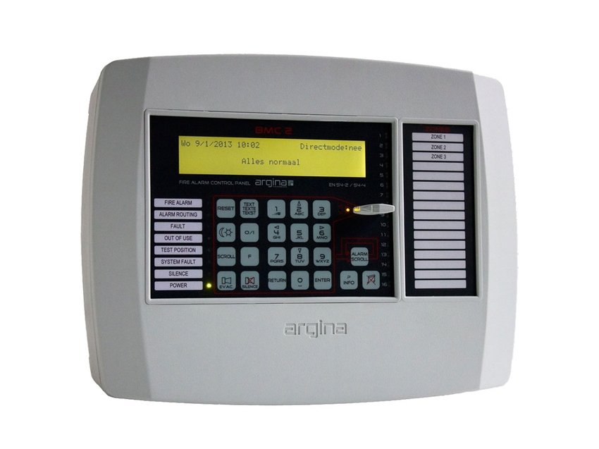
Sophisticated hardware and software have created a high-tech control panel in a compact housing. The BMC2 can be used for addressed fire alarm installations with 1 to 248 detectors.
- 2 loops with return loops (maximum 124 detectors each) or 4 loops (maximum 32 detectors each)
- Installer-friendly
- Simple operation
- Clear indications
- Large display
- One-key language change
- Conforms to EN54-2/4
- Modern and compact appearance
- 2A high-efficiency power supply
- Alarm identification with analogue analysis
- Low power electronics for better battery autonomy
- Additional control panels possible
The control unit communicates fully bi-directionally with Argina SLIM detectors, manual fire alarms, input/output modules and gas detectors, and is fully compatible with short-circuit isolators.
The control panel can be used as a 2-loop, 3-loop or 4-loop control panel:
- 2 to 124 detectors, each with a return loop
- 3 loops:
* 1 loop with return loop, up to 124 detectors
* 2 loops up to 32 detectors with no return loop - 4 loops of 32 detectors each with no return loop
An additional monitored loop for reading external controls, for example a triangular keyswitch for the fire brigade.
Up to two additional remote control panels are possible.
The language the control panel uses for messages can be changed at any time using a single key.
A precise indication of the location is given in each report (text provided by the user and up to 40 characters long).
In addition to the three standard outputs and the three standard relays, modules with 8 x 1A relays or 4x 1A + 4x 5A relays are available as options.
The control panel can be equipped with a modem module. This makes the following options possible:
- automatic telephone fire report with voice
- automatic telephone connection to compatible control rooms (SIA protocol)
- remote maintenance and updating of the control panel
The control panel can be equipped with a network card. This enables up to 8 BMC2 fire alarm control panels to be connected to each other for passing on alarm and fault messages.
The control panel has standard software installed, and the BMC2 program can be ordered as an option for further confi guration.
A laptop can be connected (USB) during commissioning or maintenance.
All internal readings can be retrieved via the laptop, for example the power consumption in the loops and the power consumption by external users.
Simple settings such as delay times can be entered from the control panel.
EN54-2 authorisation levels
- Level 1: Two keys accessible by everyone: alarm scroll, buzzer silence.
- Level 2: The other keys are accessible when the special key is inserted in the keypad and is turned in the right direction.
- Level 3: Some F-key functions are possible only after a code has been entered.
- Level 4: By connecting a laptop with the BMC-2 program.
EN54-2 options are included as standard
- 7.8 Fire alarm devices
- 7.9 Fire alarm routing equipment
- 7.10 Automatic fi re protection equipment
- 7.11 Delay of the actioning of outputs
- 7.13 Alarm counter
- 8.3 Fault signals from points
- 8.4 Total loss of power supply
- 8.9 Fault warning routing equipment
- 9.5 Disablement of each address point
- 10 Test position
- 11 Standardised I/O interface (repeater panels)
HOUSING
- Dimensions: 340x266x93 mm (width x height x depth)
- Colour: light grey (RAL7004)
- Material: ABS V0
- Cable entry: centrally-located entry area at the back of the casing. The casing creates a 21mm gap between the control panel and the wall. This allows the cables to be brought from above or below, to pass behind the casing and to enter via the central cable entry in the casing. Cable entry grommets are not required.
- Batteries: maximum 2x 7Ah batteries (180x170x78 mm)
- IP rating: IP30
- Environment:
- -5° C to +45° C
- 0 – 95% (non-condensing)
POWER SUPPLY VOLTAGE
- Primary: 230V AC / fuse 1AT
- Battery: 24V DC hermetically-sealed lead-acid batteries (2x 12V in series)
- Capacity: 1.2Ah to 7Ah
- Charging voltage: temperature-controlled (26.5 to 28V) for maximum battery life
- Charging current: max 0.86A (limited internally)
REPEATER PANEL CONNECTIONS
- Max. 2 repeater panels, cable type: XVB 3x1.5 maximum length: 150 m
POWER SUPPLY OUTPUT
- Number: 1
- Voltage: 18.5 to 28V
- Maximum current: 0.5A (electronically fused)
SIREN CONTROL
- Number: 2 circuits
- Maximum current: 0.7A (per circuit electronically fused)
- End of line resistor: 1 kilohm/1W
- Electronically fused and monitored for short circuits and line breaks
FIRE DETECTION LOOPS
- Number: 2 bi-directional each with a return loop
- Number of encoders per loop: max 124
- Short circuit detection limit:
- 0.5A
- 0.7A during alarm
RELAYS
- 3 relays: 1 switchover contact 1A/30V
- Relay PCB: 4 relays 5A + 4 relays 1A (option 2)
SWITCH LOOP
- Monitored switch loop: with resistance identification for reading 3 external switches (e.g. external Reset and Silence)
MODEM (OPTIONAL)
- 3V3 automatic telephone message with speech or SIA protocol
NETWORK (OPTIONAL)
- Connection up to 8 BMC2 fire alarm control panels


